A good basic network of forest access roads is essential for optimum forest management. In flysch, where the typical substrate contains high proportions of loam and clay, the structural engineering of forest tracks presents a particular challenge. This is because where there is water saturation - not an infrequent occurrence with the high precipitation on the northern edge of the Alps - the soil begins to "flow". The risk is exacerbated by the increase in frequency of severe precipitation events that we have seen in recent years.
Side slope stabilisation using the "Mechanically Stabilised Earth" system
A section of approx. 10 metres in length of a forest track in flysch had subsided in a landslide on a slope with a 70 % gradient, so that lorries were no longer able to use the track from this point. The running width of the track was now just 2.70 m, and the "new" side slope on the valley side fell very steeply, with a gradient of over 100 %. To re-establish a running width here that complies with safety standards, there are basically two possibilities:
- You can move the carriageway towards the mountain, or
- You can build up a new track corpus on existing firm ground (new side slope angle steeper than the original one)
There could be no question of moving towards the mountain, because the side slope was already very steep and high on the mountain side. The second option was thus chosen, and the "Mechanically Stabilised Earth" system was put to the test.
With this system, a flexible and low-elongation geogrid is used to stabilise and retain the slope. The system permits the construction of side slope angles of 60°, or with a so-called "lost" construction form, even up to 80°. In the described case, an angle of 60° was sufficient.
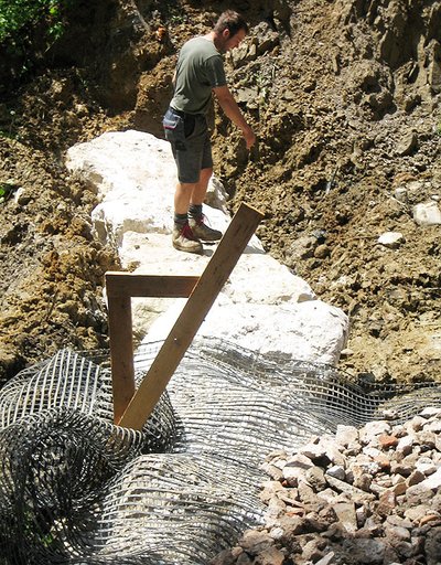
First it was necessary to excavate the damaged area across the full width of the track to a depth of approximately five metres. As it was not suitable for being re-incorporated in the road construction, the loamy excavated soil was taken away. The foot of the lower side slope was reinforced with a line of large rectangular rocks, and behind that the first layer of geogrid was laid out across the full width of the excavated area, overlapping at the sides by ten centimetres (at right angles to the direction of travel). Each six-metre length of geogrid extended beyond the row of stones by about 1.50 m (Fig. 1a). After filling with crushed stone (grain size > 6 cm) and the subsequent compacting of this layer, these one and a half metres were folded back.
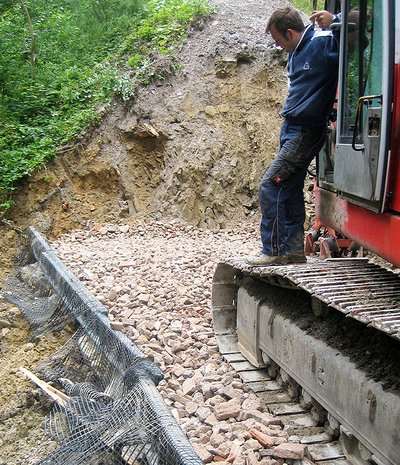
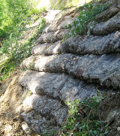
Now the next layer of geogrid was laid out, using aluminium ladders as a temporary construction form. Initially the geogrid hung out beyond these, but after filling it was again folded back over a layer that was fifty to sixty centimetres thick (Fig. 1b). This process was continued until the level of the carriageway was reached. A total of ten layers were necessary (Fig. 1c). The geogrid used had a longitudinal tensile strength of 80 kilo Newtons (kN).
The lowest layer at least must be water permeable. The rapid establishment of vegetation on the side slope protects the geogrid from UV radiation. The lowest layer was also "faced" with a layer of building elements typically used in hydraulic engineering to ensure long-term water permeability and shade.
The net costs of this measure were approx. € 10,500. The most expensive item on the cost sheet was the removal of the excavated material and the bringing of the re-filling material, at € 6,500. The actual construction work took four days.
The "stabilised earth with lost construction"
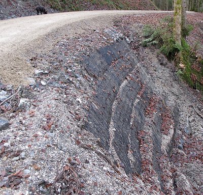
Another forest track in flysch was upgraded along a 3.6 km stretch to allow it to take heavy goods vehicles. The track has existed for a long time. It runs along a mountain stream in the valley area and is challenging in terms of drainage and side slope stabilisation (over 65 % cross slope). In one area, earlier displacement had covered the starting material in question with several layers consisting of loamy-clayey weathered flysch. The rotten wooden structure in this section of the track was to be replaced along its entire length by the "stabilised earth" system. A lost construction form in the form of angled steel meshes was used, necessitating the following eight steps:
- Excavation of the old track corpus: along a stretch of 25 m and well beyond the middle of the track and up to a depth of around 4.5 m with the bottom sloping slightly downwards
- With extremely water-saturated underlying soil: the laying of a geo-textile to separate the layers of soil
- Foot of the lower side slope (spill): The setting of a row of rough-hewn rectangular rocks and laying of the lowest layer of the geogrid (80 kN longitudinal tensile strength; 4 m into the bottom of the track, 2 m to be folded over later)
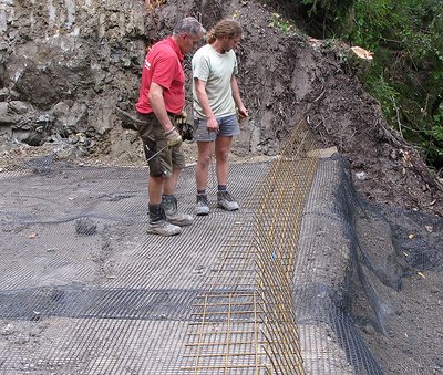
- Lost construction form: Incorporation of angled construction steel elements (2.20 m x 1.30 m, angle of bend 60°) on the row of rough-hewn stones at the foot of the slope (Fig. 2a)
- Filling: filling and compacting of first stabilising layer with water permeable material (crushed stone, grain size > 6 cm), to a thickness of approx. sixty centimetres
- Wrapping under tension: wrapping of the overhanging geogrid around the construction form preferably under light tension; slight heaping of the fill material to fix the tension.
- Further layers: Construction of further layers along the lines of the first, until the roadway level was reached (in this case six layers)
- Establishment of vegetation cover
It was possible to stabilise the section of road completely in one and a half weeks (Fig. 2b). The total net costs were € 7,500 including excavation of the unsuitable earth and the bringing and incorporation of the large rough-hewn rocks, geogrid and fill material.
Technical slope stabilisation by means of back-anchored sprayed concrete lining
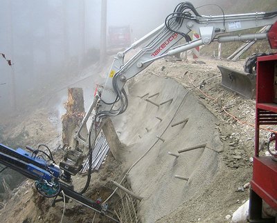
At one place on a forest track in flysch, the running surface had developed bumps over a length of ten metres. The slope inclination in this section is approximately 75 %. After a few weeks, a 35 m-long crack then formed in the top layer. The "Mechanically stabilised earth" system was not sufficient here to stabilise the track corpus, as the cause of movement in the slope was the emergence of slope water around 30 m below the road. The slope was stabilised using a stabilised, 20 cm thick sprayed concrete lining, four to five metres high, 20 cm thick and back-anchored in two-rows (Fig. 3).
The net costs of the construction work amounted to a total of € 87,000. This is the equivalent of € 580 per square metre of sprayed concrete lining.
Summary
The elaborate, costly procedure of stabilising the side slope with sprayed concrete will certainly only be used in absolutely extreme cases. The "stabilised earth" system - with or without lost construction forms - can be used to stabilise slopes of up to 80° without difficulty and saves both time and costs. The next few years will show whether the "stabilised earth" system will also prove workable in practice.

